A 3 MW grid-connected photovoltaic plant
Array design, electrical configuration and layout follow the licensed capacity and the 45,000 m² licensed footprint exactly. Energy estimates come from PVsyst 7.4 simulation using Meteonorm 8.1 climate data for the precise site coordinates.
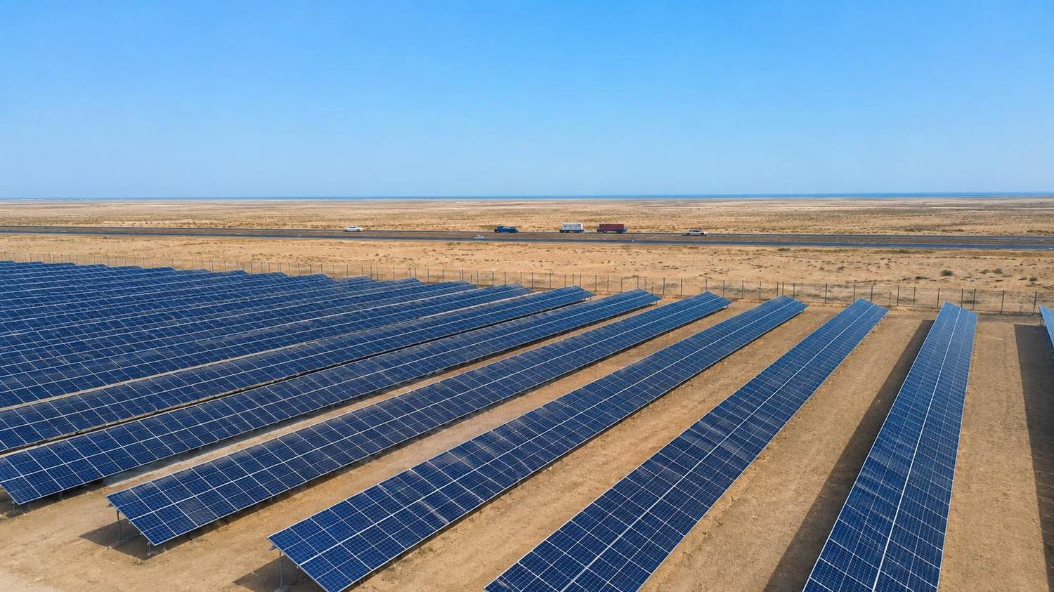
| Plant type | Grid-connected photovoltaic, fixed-tilt |
|---|---|
| Installed DC power | 3,276 kWp |
| Rated AC power | 2,945 kW |
| DC/AC ratio | 1.11 |
| Modules | 5,040 units, 650 W bifacial monocrystalline |
| String layout | 168 strings × 30 modules in series |
| Inverters | 19 string inverters of 155 kW |
| Transformers | 2 × 1,600 kVA, 0.6/20 kV |
| Tilt and orientation | 25° facing south, zero azimuth |
| Row pitch | 8 m centre to centre |
| Global horizontal irradiance | 2,060 kWh/m² per year |
|---|---|
| Irradiance on optimum tilt | 2,269 kWh/m² per year |
| Optimum tilt angle | 28° facing south |
| Design specific yield | 1,780 kWh per kWp |
| Performance ratio | About 84.5% |
| First-year energy | 5,830 MWh |
| 20-year cumulative energy | 111,300 MWh |
| Annual degradation | 0.55% |
Yield figures are simulation-based estimates and will be finalised after on-site measurement and detailed study.
Land and location
The site boundary is traced in orange on the satellite map. The whole 96,791 m² parcel is owned by the company; phase one occupies 45,000 m² on its western side.
Click the map to zoom, or use the button above it to open the same location in Google Maps.
| Administrative location | Dovireh, Chaghadak district, Bushehr county, Bushehr province |
|---|---|
| Centre coordinates | 29°01′40.2″ N, 51°03′21.6″ E |
| Elevation | About 11 m above sea level |
| Total site area | 96,791 m² — owned by the company |
| Phase one footprint | 45,000 m² on the western side |
| Phase two reserve | About 51,800 m² to the east, to a combined 7 MW |
| Road access | About 500 m to the Bushehr–Borazjan highway |
| Distance to Bushehr city | About 20 km |
| Distance to grid connection | About 6 km to the medium-voltage network |
| Topography | Flat with a gentle southward slope, no shading obstacles |
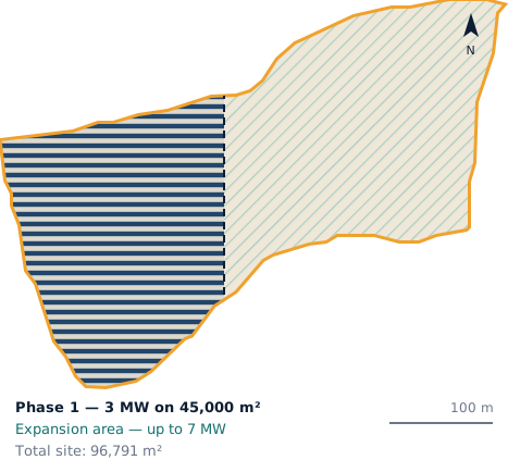
Phase one, 3 MW on 45,000 m² to the west; the remainder is reserved for phase two to a combined 7 MW.
Site engineering considerations
Corrosivity
Gulf proximity places the site in class C4/C5; hot-dip galvanised structures at 80 µm minimum with stainless fixings.
Dust
3% annual soiling loss assumed, managed by a cleaning programme of at least eight cycles per year.
Geotechnics
Rammed pile foundations; pull-out testing and soil boreholes are required before construction.
Physical security
Full perimeter fencing, site lighting, CCTV and an intrusion alarm system; included in the capital estimate.
Water supply
No surface water on site; wash water from a licensed well or tanker into a 50 m³ tank.
Far shading
Effective horizon height averages 1.4°, costing about 0.16% of yield.
Row shading
At an 8 m pitch, about 1% inter-row shading loss is included in the model.
From array to grid
Inverter output is stepped up through two 1,600 kVA transformers to 20 kV and carried by an approximately 6 km line to the regional medium-voltage network.
Construction programme — 12 months
PermittingMonths 1–2
Licence renewal, grid connection agreement, statutory clearances
Baseline studiesMonths 1–3
Detailed survey, geotechnical investigation, ramming test
Engineering and procurementMonths 2–4
Detailed design, tender documents, contractor selection
Equipment supplyMonths 3–7
Ordering, letters of credit, shipping and customs
Site preparationMonths 4–6
Grading, access road, fencing, substation foundations
Array installationMonths 5–9
Pile ramming, structure and module installation, DC cabling
Electrical worksMonths 8–10
Inverters, substation, 20 kV line, monitoring system
Testing and commissioningMonths 10–12
Acceptance testing, synchronisation, first energy
Environmental and employment effects
Request the full technical pack
The feasibility study, licence summary, site map and simulation results are shared with investors after an initial conversation.